|
Measuring Clocks and Watches
Magnetic Sensors Pros
Cons
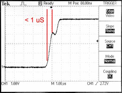
To eliminate the effects of changing light levels you can use a Hall effect magnetic sensor. These semiconductor devices detect a magnetic field to trigger the timer. A tiny permanent magnet is placed at the tip of the pendulum to trigger the sensor. This oscilloscope trace shows the output of a magnetic sensor. The rise time is even steeper than the optical sensor, reaching the three volt threshold in less than one microsecond. Like the optical sensor, this offset is consistent from one beat to the next. And the Hall sensor is unaffected by ambient light.
But there are hazards with a magnetic sensor too. The magnet you place at the tip of the pendulum will add a tiny amount of mass and slow the pendulum down a tiny bit. As long as you leave the magnet in place, it doesn’t matter. The risk is that you have some magnetic material close to the magnet. For example, if you’re using a steel clamp to hold the magnetic sensor, the magnet may be attracted to the clamp and slow down the pendulum. This can be avoided by using non magnetic materials around the sensor. In addition, the magnetic field emanating from a single magnet spreads out as it reaches around to the opposite pole of the magnet. This means the width of the field, and therefore the trigger point, depends on the distance of the magnet from the sensor. This has the same effect as changing light levels with an optical sensor. This graph shows the effect of distance between the sensor and magnet. Each vertical red line represents the duration of a Hall sensor trigger. At the beginning of the graph we can see the trigger width when the sensor is 1/16 inch away from the magnet. The middle of the graph shows the trigger width if the sensor is moved 1/4 inch away from the magnet.
The trigger width is shorter when the magnet is farther away. This could become an issue if the pendulum gets longer on warm days and brings the magnet closer to the sensor. Sudden changes are unlikely, but creep could occur. In this, as in all measurement questions, you would need to analyze the details of the situation to see if the scale of the effect would become a problem or not. This diagram illustrates a simple magnet at the tip of a pendulum bob, showing how the lines of magnetic force are generally unconstrained and arc out to join opposite poles of the magnet. Where the lines cross the detector, and when the detector triggers, changes with position. If the positions don’t change, the trip point is exceptionally consistent with magnetic sensors.
There’s a way to minimize this variation in the magnetic field, and that’s to form a closed magnetic circuit. Magnetic fields can be thought of as flowing like electricity. They want to connect north to south just like an electrical circuit wants to connect positive to negative. The conductors of magnetic circuits are magnetic metals, like iron. If you “short circuit” the north and south poles of a magnet with an iron bar, the field is contained within the iron. If you put a gap in that iron bar, the magnetic field will jump across that gap like an electric spark jumps a gap between two wires. This diagram illustrates a magnetic circuit for a sensor at the tip of the pendulum. The magnetic lines of force pass through the iron structure until they’re forced to jump the remaining gap. The field will be consistent across this gap, and stray magnetic fields won’t reach out to magnetic materials in the vicinity to effect the rate of the pendulum.
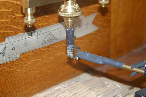
This photograph shows a simple magnetic gap triggering a Hall effect sensor. Tiny neodymium magnets are stuck to the inside faces of two steel strips. This produces a magnetic sensor that’s much more consistent.
|