|
Experimental Electromagnetic Clocks I have been experimenting with the fabrication of electromagnetic clocks using custom electronic circuits to impulse the pendulum and drive the dials. My method of impulse is based on the design invented by F.M. Fedchenko in the 1950's. Fedchencko designed a drive circuit for his ultra-precision clocks that consisted of two separate coils. One of these coils is the "sense" coil. When the magnet swings over it, a current is induced in the coil. This current is amplified by a transistor, and then made to flow in the other coil, which is the "drive" coil. The current flowing in the drive coil creates a magnetic field which interacts with a permanent magnet on the pendulum to give an impulse. This action happens once per period, and keeps the pendulum swinging at it's own natural rate. I have designed my own version of this circuit to drive my clocks.
The electric dial is made from the stepper motor in a conventional quartz clock. An electronic circuit in the base of my clock sends signals to this motor to drive the hands. This gives my little clock a big advantage over the Bulles and Pooles that preceded it. My pendulum does not need to drive a mechanical gear train, and is required to do no more than swing freely. The pendulum rod is 1/8" invar. The suspension is a 3/16" strip of .004" spring steel, and hangs from a slit cut in a horizontal length of brass rod. The bob is a 2" length of 1" brass rod that weighs about seven ounces. The bob is threaded, and can be raised or lowered by turning it on the pendulum rod. Beneath the bob is the small permanent magnet that forms part of the electromagnetic drive. The magnet is also mounted in a threaded fixture. This allows me to raise or lower it to adjust the magnetic gap. A drop of Loctite holds it in place once it is properly positioned. The magnet itself is a little unusual in that it is in the form of a small brick, but the poles are not at the ends. Rather, the brick forms a compact horseshoe structure with the north and south poles pointed towards one flat side of the brick. This maximizes the magnetic force in the direction of the coils, which are positioned just under the surface of the wooden base.
The electronic control circuit One of the problems inherent in battery clocks is that the voltage changes as the batteries age. This will tend to make the pendulum swing less widely and change the rate of the clock. I wanted both battery operation and constant voltage, so one of the improvements I made in my electronic design was to implement a very low power constant voltage source for the drive coil. This uses technology that was not available to Fedchenko. His clocks ran on mercury batteries because they have a very flat discharge curve. This clock uses a diode reference to hold the impulse voltage at exactly 2.5 volts regardless of the battery voltage. Fedchenko used a variable resistor to adjust the amplitude of swing in his clocks. I have done the same thing, but because I don't have the benefit of an isochronous suspension, I am also able to fine tune the rate in this way. I placed a small variable resistor in series with the drive coil. This allows me to alter the portion of the impulse voltage that gets to the coil, which in turn allows me to trim the rate very finely with no physical disturbance to the pendulum. In practice, I get the rate as close as possible by adjusting the bob on the threaded rod. This will get within 20 or 30 microseconds of the correct beat time. After the pendulum has settled for an hour or so, final adjustment can be made with the variable resistor. This is a major improvement over the use of tiny weights on a tray because it can be done without removing the glass dome or disturbing the pendulum whatsoever. It's interesting to note that this adjustment works in the reverse direction of what you would expect. In other words, an increase in amplitude speeds the clock. I expect this is caused by the domination of escapement error over circular error in the magnetic drive circuit. I have been told that Fedchenko clocks behave the same way until the isochronous suspension is correctly adjusted. I have not investigated ways of reducing this error because it would reduce my ability to fine tune the clock with a change in voltage. My electronic circuit also includes an output to drive the MicroSet Clock Timer directly, eliminating the need to position sensors on the pendulum or disturb the clock by running it with the dome removed. I'm now making a refined version of this electromagnetic drive circuit available for sale. Click here for more information. Software "Gear Train" The conversion of 32 beats to 13 seconds is accomplished by the microprocessor in the base of the clock. It simply counts the beats of the pendulum and generates signals for the electric dial when they are needed. The microprocessor uses much less electricity than the drive coil or the slave dial, and the four "AA" batteries in my clock should last for well over a year. It's incredibly convenient to have a programmable microprocessor in the drive circuit. I had planned for my pendulum to have a period of .4444 seconds, but I found that the bob I was going to use didn't look good, and I changed my design to a bob that was much taller than originally planned. This raised the center of gravity of the pendulum and increased the rate, which would have been a significant inconvenience for a mechanical gear train. To make this change in a mechanical clock would have required new gears and plates. With the microprocessor, I simply told the program to advance13 seconds in 32 beats rather than four seconds in nine beats. When I make another clock, if I'd like it a little taller, or a little shorter, it will always be near some integer relationship that I can set in the software. Performance
The accuracy of this clock far exceeds my measurements of Bulle and Brillie half second battery clocks. It is nearly as good as my seconds beating experimental clocks, and has beat times within one microsecond of each other on a 60 beat average. Because the bob is unusually large and uncompensated, thermal effects cause the clock to gain about half a second on warm days, and lose it in the cool night. The illustrations below compare the performance of my half-second EM3 with half second Bulle, Brillie, and ATO battery clocks. It will be seen that my own clock runs significantly better than any of the antecedents. Much of this benefit can probably be attributed to the fact that my clock uses an electric dial and doesn't need to drive a gear train. The Bulle clock is particularly unstable. It's my belief that this is due to the isochronism spring, which greatly disturbs the natural motion of the pendulum. I have measured several Bulles and they all have similar poor performance. To be fair, none of them are new and it's possible that they performed better in 1930.
In the following four graphs, each clock is scaled to reveal its fluctuations clearly. Each graph shows two days of running, and each clock was measured with 60 second averages of its half second beat time. The horizontal scale has been compressed so that the entire two day interval will show.  The Brillie clock is quite erratic. Each reading is likely to be different from it's neighbors by a rate change of about 39 seconds per day (this is the MicroSet "Instability" factor). Over the two days shown the rate also fluctuated on a longer scale, running slow near the beginning and fast near the end. The Brillie clock is quite erratic. Each reading is likely to be different from it's neighbors by a rate change of about 39 seconds per day (this is the MicroSet "Instability" factor). Over the two days shown the rate also fluctuated on a longer scale, running slow near the beginning and fast near the end.Each grid line represents a rate change of 200 microseconds, or 34 seconds per day  The Bulle clock is even worse than the Brillie. Each reading is likely to vary from it's neighbors by 60 secs per day (the MicroSet "Instability" factor). The Bulle seems to run somewhat consistently for a while, and then make sudden jumps to a new rate. The Bulle clock is even worse than the Brillie. Each reading is likely to vary from it's neighbors by 60 secs per day (the MicroSet "Instability" factor). The Bulle seems to run somewhat consistently for a while, and then make sudden jumps to a new rate.
Each grid line represents a change of 250 microseconds, or 43 seconds per day.  The ATO clock performs much better than the previous two. Each reading is likely to vary from it's neighbors by 8 seconds per day (the MicroSet "Instability" factor). It's not obvious in this compressed scale, but the graph reveals that the clock speeds up and slows down about 30 microseconds each hour with the rising and falling of the minute hand. The ATO clock performs much better than the previous two. Each reading is likely to vary from it's neighbors by 8 seconds per day (the MicroSet "Instability" factor). It's not obvious in this compressed scale, but the graph reveals that the clock speeds up and slows down about 30 microseconds each hour with the rising and falling of the minute hand.
Each grid line above represents a change of 19 microseconds, or 3 seconds per day.  The rate of my EM-3 clock never varies by more than 15 microseconds in two days, and individual 60 second averages are within one microsecond of each other (a MicroSet "Instability" factor of 0.0). The wave shape seen above is thermal response to temperature fluctuations in my living room. The rate of my EM-3 clock never varies by more than 15 microseconds in two days, and individual 60 second averages are within one microsecond of each other (a MicroSet "Instability" factor of 0.0). The wave shape seen above is thermal response to temperature fluctuations in my living room.
Each grid line represents a change of three microseconds, or half a second per day. The final graph shows all four clocks in the same scale. You can see quite clearly how much more erratic the Bulle and Brillie clocks are. The ATO is running nearly flat in this scale, and there is barely a wobble in my EM3.
|
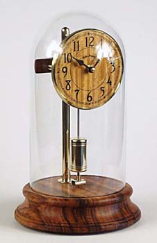 My first "Fedchenko drive" clock is shown here. I decided to make a small clock, derived very loosely from early battery electrics like the Bulle and Poole. The base is turned wood, hollowed out to contain the electronic components and batteries. A nine inch brass rod, which supports the electric dial and pendulum, is bolted to the top of the base. The entire mechanism is covered by a 10" glass dome.
 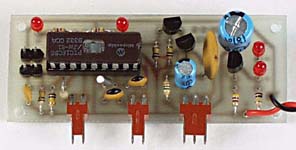 The Fedchenko design used a very simple circuit to drive the pendulum. I have elected to use a modern microprocessor to manage my clock because it gives me programmable control of the several switching functions I need. Everything it does could have been accomplished with more primitive components, but it makes design changes and improvements possible by changing the program rather than the circuit.
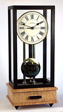 I was encouraged by the performance of this clock, and decided to make a larger model with a half second pendulum. This could then be compared more directly with the larger Bulle and Brillie clocks I have. "EM3" is a half second electromagnetic clock made with the same basic drive components and slave dial. The base of the clock is fiddle-back maple, the cover is ebony and glass. The electronic controller and batteries are contained in a drawer in the base of the clock. The pendulum rod is wood, the bob a brass disk supported at its bottom.