|
A Seconds Beating Electromagnetic ClockThis page describes an electromechanical clock of original design, made in 1998
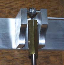
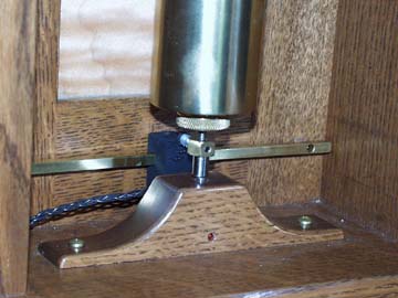
The Pendulum This pendulum is a replacement for the original one, which had a lead-filled cylindrical bob on a wooden rod. It's interesting to note that the new pendulum is three or four times more stable under temperature changes than the first one was. The dial is painted metal with a lacquered face. You will note the use of a separate seconds bit. The slave mechanism is made from the stepper motor out of a quartz clock which I drive with my own electronics. I deliver a pulse to the main motor and the seconds bit once on each passage of the pendulum. The hands can be adjusted (advanced or prevented from advancing) with push buttons on the electronics card. The Suspension The Drive The sensor I'm currently using is a Hall effect device, chosen because it has lower current consumption than an optical detector and is immune to ambient light conditions. This is a non-critical choice, however, and optical sensors could be used instead. The coil housing and sensor can be seen below. The electronic controller is an original design, made for this clock. It uses a PIC microprocessor and has an LCD screen, three push buttons, and a variety of control inputs and outputs. It can be powered with batteries or an AC adaptor and has outputs to drive the impulse coil, the slave dial, and the MicroSet clock timer. Two inputs allow operation from one or two optical or Hall effect sensors. Note that the computer is not used to control the rate; that's determined entirely by the tuned pendulum. 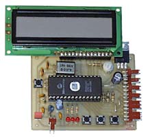
The microprocessor makes it easy to change the method of operation without making any physical changes to the clock. The program senses the left-to-right movement of the pendulum and drives the impulse coil for 40 milliseconds just before center of swing. This causes the pendulum to reach an equilibrium of about one and a half degrees of semi-arc. The operator can use the push buttons and LCD screen to customize these operating parameters. For example, it's easy to change the duration of impulse from 40 milliseconds to any other duration, or change the frequency of impulse from once per period to as infrequently as you like. Such control will allow you to trim the rate without opening the case to adjust the weight tray. Software could also be written to support operation by maintaining constant velocity or by maintaining constant amplitude. Performance
Bob Holmstrom has analysed this data and prepared a couple of graphs that suggest the rate changes in this clock over 81 days are due to "random walk" (random noise). Click here to see his graphs. Bryan Mumford Revised: 01-17-16
|
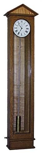 The clock is made to hang on a wall and stands 58" tall. The case is made from quarter sawn oak that has been stained to resemble turn-of-the-century antique clocks. It has accents of figured maple in the top and back panels, and the door is glazed with beveled glass. At the bottom of the case is a small compartment for holding the electronics.